
LED Dimming Engine: Switch-Mode Dimmable LED Driver Solution Based on Microchip's PIC16F1779 MCU
Switch-mode dimmable LED drivers are known for their high efficiency and control over LED current. They can also provide dimming capabilities, enabling end users to create fantastic lighting effects while reducing power consumption.
8-bit microcontroller (MCU) implementations can provide the necessary building blocks to create solutions that support communication, customization, and intelligent control. In addition, independent peripheral integration provides significant flexibility compared to pure analog or ASIC implementations and enables innovation that expands lighting product functionality and provides product differentiation. Features such as predictive failure and maintenance, energy monitoring, color and temperature maintenance, and remote communication and control are just some of the advanced features that make smart lighting solutions more attractive.
Although LED drivers have many advantages over previous lighting solutions, there are also challenges in their implementation. But don't worry, after reading this article, you will understand how to use 8-bit MCUs to alleviate design challenges and create high-performance switch-mode LED driver solutions with capabilities that exceed traditional solutions.
An 8-bit microcontroller can be used to independently control up to four LED channels, a feature not available in most off-the-shelf LED driver controllers. In Figure 2, an LED dimming engine can be created by leveraging the peripherals available in a microcontroller. Each of these engines has an independent closed channel that can control a switch-mode power converter with little or no intervention from the central processing unit (CPU). This leaves the CPU free to perform other important tasks such as supervisory functions, communications, or additional intelligence in the system.
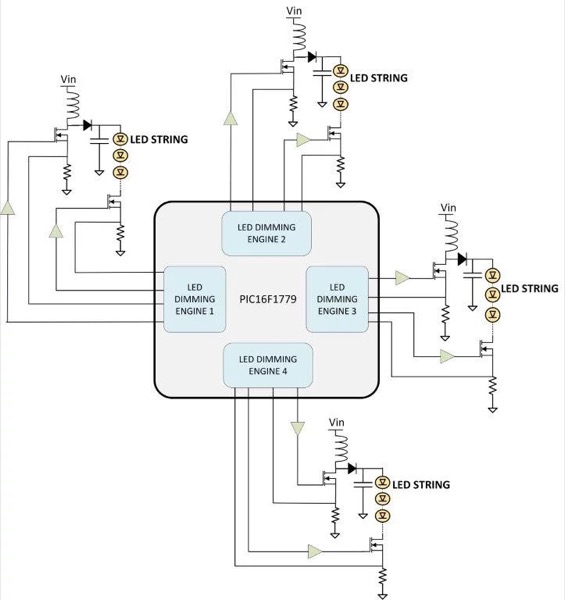
Figure 2: Schematic of four LED strings controlled by a Microchip PIC16F1779 8-bit microcontroller
LED Dimming Engine
In Figure 3, a current-mode boost converter-based LED driver is controlled by an LED dimming engine. The engine consists primarily of independent peripherals (CIPs) such as a complementary output generator (COG), digital signal modulator (DSM), comparator, programmable ramp generator (PRG), operational amplifier (OPA), and pulse width modulator 3 (PWM3). Combining these CIPs with other on-chip peripherals such as a fixed voltage regulator (FVR), digital-to-analog converter (DAC), and capture/compare/PWM (CCP) completes the engine. The COG provides high-frequency switching pulses to MOSFET Q1 to allow energy and supply current to be transferred to the LED string. The switching period of the COG output is set by the CCP and the duty cycle, maintaining a constant LED current and determined by the comparator output. The comparator generates an output pulse whenever the voltage across Rsense1 exceeds the output of the PRG module. The input of the PRG is derived from the OPA output in a feedback circuit and is configured as a slope compensator to counteract the effects of subharmonic oscillations inherent at duty cycles greater than 50%.
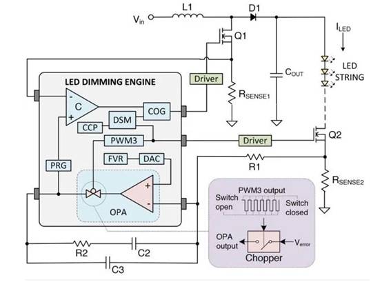
Figure 3: LED dimming engine
The OPA module is implemented as an error amplifier (EA) with a Type II compensator configuration. The FVR is used as the DAC input to provide a voltage reference to the OPA non-inverting input according to the LED constant current specification.
To achieve dimming, PWM3 is used as a modulator for the CCP output while driving MOSFET Q2 to quickly cycle the LED on and off. Modulation is performed by the DSM module and the modulated output signal is fed to the COG. PWM3 provides pulses with a variable duty cycle, controlling the average current of the driver, which effectively controls the brightness of the LED.
LED dimming engines not only fulfill the functions of a typical LED driver controller, but also have the function of solving the typical problems brought by LED drivers. Now we will introduce these problems and how to avoid them using LED dimming engines.
Flicker
Flicker is one of the challenges that a typical switch-mode dimmable LED driver may face. While intentional flicker can be a fun effect, when LEDs flicker unintentionally, it can ruin the lighting design that users want. To avoid flicker and provide a smooth dimming experience, the driver should perform dimming steps from 100% light output all the way down to the low-end light level with a continuous and smooth effect. Since LEDs respond immediately to current changes and have no damping effect, the driver must have enough dimming steps so that the eye does not perceive the change. To meet this requirement, the LED dimming engine uses PWM3 to control the dimming of the LED. PWM3 is a 16-bit resolution PWM with 65536 steps from 100% to 0% duty cycle, which ensures smooth lighting level transitions.
LED Color Temperature Variation
LED drivers can also change the color temperature of the LED. This color variation can be noticeable to consumers and undermine claims about the high-quality lighting experience of LEDs. Figure 4 shows a typical PWM LED dimming waveform. When the LED is turned off, the LED current gradually decreases due to the slow discharge of the output capacitor. This event can cause LED color temperature variation and higher power consumption.
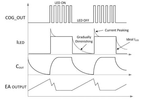
Figure 4: LED Dimming Waveform
The slow discharge of the output capacitor can be eliminated by using a load switch. For example, in Figure 3, the circuit uses Q2 as a load switch, and the LED dimming engine synchronously turns off the COG PWM output and Q2 to cut off the path of the decaying current and allow the LED to turn off quickly.
Current Peaks
When a switch-mode power converter is used to drive LEDs, the feedback circuit is used to regulate the LED current. However, during dimming, the feedback circuit may generate current peaks if the operation is not handled properly (see Figure 4). Recalling Figure 3, when the LED is on, current is delivered to the LED and the voltage across RSENSE2 is fed to the EA. When the LED is off, no current is delivered to the LED and the RSENSE2 voltage becomes zero. During the dimming off period, the EA output increases to a value and overcharges the EA compensation network. When the modulated PWM is turned on again, it takes several cycles to recover while a high peak current is driven to the LED. This current peak condition shortens the life of the LED.
To avoid this problem, the LED dimming engine allows PWM3 to be used as an override source for the OPA. When PWM3 is low, the output of the EA is tri-stated, completely disconnecting the compensation network from the feedback loop and maintaining one point of stable feedback as the charge stored in the compensation capacitor. When PWM3 is high and the LED turns on again, the compensator network is reconnected, the EA output voltage instantly jumps to the previous stable state (before PWM3 was low), and the LED current setpoint is restored almost instantly.
Complete Solution
As mentioned earlier, the LED dimming engine can operate with little or no CPU intervention. Therefore, while all the work of controlling the LED driver is offloaded to the CIP, the CPU has plenty of bandwidth to perform other important tasks. By processing the sensed input and output voltages, protection functions such as undervoltage lockout (UVLO), overvoltage lockout (OVLO), and output overvoltage protection (OOVP) can be implemented. This ensures that the LED driver operates within the required specifications and protects the LED from abnormal input and output conditions. The CPU can also process thermal data from sensors to implement thermal management of the LED. Additionally, when setting the dimming level of the LED driver, the CPU can handle triggers from simple external switches or commands from serial communications. At the same time, the parameters of the LED driver can be sent to external devices via serial communications for monitoring or testing.
In addition to the above features, designers can add more intelligence to their LED applications, including communications such as DALI or DMX and control customization. Figure 5 shows an example of a complete switch-mode dimmable LED driver solution using an LED dimming engine.
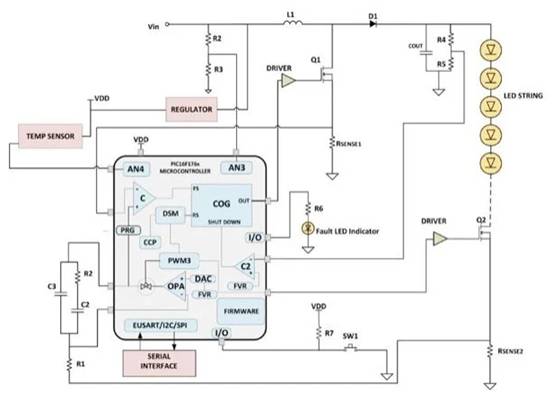
Figure 5: Switch-mode dimmable LED driver solution
Conclusion
LED dimming engines can be used to create effective switch-mode dimmable LED drivers. Efficiency is equivalent to its ability to drive multiple LED strings, provide efficient energy, ensure the performance of the LEDs, maintain a long life of the LEDs, and add system intelligence.